Writing a PS2 emulator, the guide: Part 1, an intro to the hardware
So, I thought that a great first idea for a blog post was a Simias-style guide for writing a PS2 emulator in C++. In this multi-part series, I’ll do my best to walk whoever is reading this through the beginnings of a PS2 emulator all the way to first output running the 3-stars demo.
A word of warning before we dive in: It will take a lot of work to follow this. The PS2 is not a simple beast, and achieving any sort of speed is very difficult, requiring a ton of optimizations. But, if you stick with it, it is an incredibly rewarding experience. A word of warning, you will need to have at least a passing familiarity with MIPS before you start, along with some experience writing emulators.
The hardware
The PS2 is very well known, and one of the best selling video game consoles of all time. But what makes it tick under the hood? Let’s take a look.

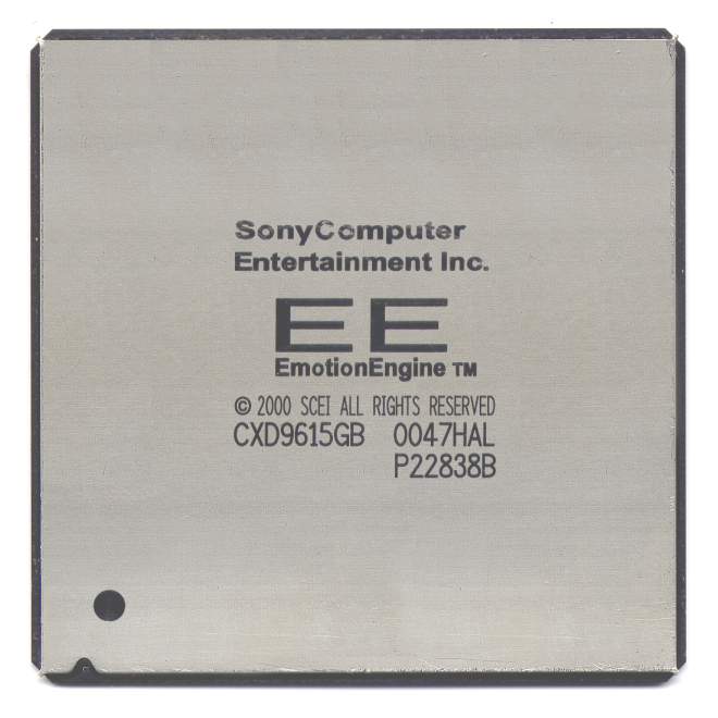
First off, there is the Emotion Engine (EE). It’s a custom MIPS-based RISC core clocked at about 295Mhz. It’s based upon the MIPS R5900, and it implements MIPS III and most of the MIPS IV ISA. It has also been modified to support 128-bit integers, along with an entirely new SIMD instruction set dubbed “MMI” by Sony. It’s quite a lot of power packed into one chip, but it would be useless without accelerators. So, alongside the standard COP0 for exceptions, Sony also included an FPU on COP1 for single-precision floating-point math, and a 128-bit SIMD coprocessor known as Vector Unit 0, or VU0, on COP2.
Let’s take a closer look at VU0 and it’s brother, VU1. VU1 and VU0 can both be run in what is known as “micro mode”, i.e. as an entirely separate processor, running calculations parallel to the EE. However, VU0 can also run in “macro mode”, where it is a coprocessor attached to the EE. The Vector Units are a PITA to emulate, because of their relatively exposed pipeline, and because games abuse them to no end to squeeze every drop of performance out of this console they can.
Also attached to the EE is an intelligent Direct Memory Access Controller, or DMAC. It is able to chain transfers together, moving data between components with almost zero input. This allowed game developers to chain together packets of graphics data to be uploaded to the Vector Units, for example.
The next component to examine is the Graphics InterFace, also called GIF. This small component has the job of decoding and unpacking graphics data, usually textures, before shipping them off to the GPU. This can also be used to draw shapes, but it’s incredibly slow.
The Graphics Synthesizer is the PS2’s GPU. It’s a fixed-function rasterizer designed to draw polygons very quickly, and it’s pretty good at it’s job. It’s clocked at 147Mhz, and it can process around 300k polygons at 30fps. It also supports up to 32-bit textures, along with builtin depth buffer support (looking at you, PSX). The GS also houses the CRT controller, which transforms the GS’s output into a format TVs can understand.
The PS2 comes equipped with 32 MB of RDRAM clocked at 400MHz, and a 4 MB BIOS ROM.
You may have noticed one thing that is conspicuously absent: access to peripherals. Here’s where Sony did something interesting: The PSX’s processor is present in the PS2, clocked at 33.86MHz, and renamed to “IOP” (Input/Output Processor). It’s sole purpose is to stream data between the EE and the peripherals of the system. The IOP has access to the CDVD drive, memory cards, controllers, SPU2, and a further 2 MB of RAM.
The two processors communicate using an RPC connection via a two-way hardware FIFO and a series of registers collectively referred to as the “SIF” (Subsystem InterFace). Using DMA transfers, the two can communicate rather quickly, allowing the IOP to rapidly send data wherever the EE needs it.
And with that, part 1 comes to a close. In the next part, we’ll actually start writing some code! I hope you enjoyed, and see you next time.